画图组件jgraphx项目元素连接实践(四)
Java画流程图admin 发布于:2023-07-30 14:58:05
阅读:loading
前面一些文章整体上对流程图组件jgraphx的简单介绍和自带示例的展示,同时也对它的导出进行了实践,实际上仔细点的话里面的东西还是比较多的,但是需要深入的去挖掘它,所以站在我的水平面高度上我将会对我认为有用的一些示例进行研究,前篇是对连接线的实践,实际本篇也与连接线有关,多出来了与元素连接的实现,本篇文章将对元素和元素连接线做详细的实践。
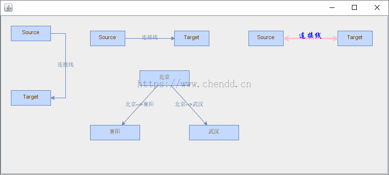
元素(框)和连接线是一个流程图组成的根本,也是最基本应包含的组成,本次示例将来稍微全面的实现一些元素框和一些连接线的示例,个人认为示例的知识范围也比较全面,参考如下图所示:


(1)上下连接两个矩形元素,连接线至上而下,线条包含文本;
(2)左右连接两个矩形元素,连接线从左到右;
(3)连接线的样式自定义,可以设置连接线的高度、线条颜色、字体、字体大小、文字颜色、双向箭头等;
(4)一个元素同时连接两个元素的实现,默认它的其实元素的点不为同一个起点,即上图中的北京连接襄阳和武汉时的起始点不一样;
(5)一个元素同时连接两个元素的实现,设置它们的起始连接点为同一个点,我个人觉得也许那样看起来更好点一些,所以经过摸索后我做到了;
(1)自定义多样式的连接线
graph.getModel().beginUpdate();
try {
    // 添加元素
    Object source = graph.insertVertex(parent, null, "Source", 500, 30, 70, 30);
    Object target = graph.insertVertex(parent, null, "Target", 680, 30, 70, 30);
    // 添加连接线
    mxCell edge = (mxCell) graph.insertEdge(parent, null, "连接线", source , target);
    edge.getGeometry().setTerminalPoint(new mxPoint(0, 0), true);
    edge.getGeometry().setTerminalPoint(new mxPoint(80, 30), false);
    edge.getGeometry().setRelative(true);
    edge.setStyle(mxConstants.STYLE_EDGE + "=" + mxConstants.EDGESTYLE_ENTITY_RELATION);
    edge.setStyle(edge.getStyle() + ";" + mxConstants.STYLE_STARTARROW + "=" + mxConstants.ARROW_CLASSIC);
    //线条颜色
    edge.setStyle(edge.getStyle() + ";" + mxConstants.STYLE_STROKECOLOR + "=pink");
    //线条宽度
    edge.setStyle(edge.getStyle() + ";" + mxConstants.STYLE_STROKEWIDTH + "=3");
    //文字颜色
    edge.setStyle(edge.getStyle() + ";" + mxConstants.STYLE_FONTCOLOR + "=blue");
    //字体
    edge.setStyle(edge.getStyle() + ";" + mxConstants.STYLE_FONTFAMILY + "=华文行楷");
    //字体大小
    edge.setStyle(edge.getStyle() + ";" + mxConstants.STYLE_FONTSIZE + "=16");
    //文字居中(居左、居右)
    edge.setStyle(edge.getStyle() + ";" + mxConstants.STYLE_ALIGN + "=" + mxConstants.ALIGN_CENTER);
    //文字物理显示位置(居上、居下)
    edge.setStyle(edge.getStyle() + ";" + mxConstants.STYLE_VERTICAL_ALIGN + "=" + mxConstants.ALIGN_MIDDLE);
} finally {
    graph.getModel().endUpdate();
}
(2)一个元素连接另外两个元素
graph.getModel().beginUpdate();
try {
    // 添加元素
    Object a = graph.insertVertex(parent, null, "北京", 280, 110, 100, 30);
    Object b = graph.insertVertex(parent, null, "襄阳", 180, 220, 100, 30);
    Object c = graph.insertVertex(parent, null, "武汉", 380, 220, 100, 30);
    // 添加连接线
    mxCell ab = (mxCell) graph.insertEdge(parent, null, "北京-->襄阳", a , b);
    mxCell ac = (mxCell) graph.insertEdge(parent, null, "北京-->武汉", a , c);
} finally {
    graph.getModel().endUpdate();
}
(3)一个元素连接另外两个元素,设置相同的起始点
graph.getModel().beginUpdate();
try {
    // 添加元素
    Object a = graph.insertVertex(parent, null, "北京", 280, 110, 100, 30);
    Object b = graph.insertVertex(parent, null, "襄阳", 180, 220, 100, 30);
    Object c = graph.insertVertex(parent, null, "武汉", 380, 220, 100, 30);
    // 添加连接线
    mxCell ab = (mxCell) graph.insertEdge(parent, null, "北京-->襄阳", a , b);
    mxGeometry abGeometry = ab.getGeometry();
    abGeometry.setRelative(true);
    ab.setSource(null);
    mxPoint abSourcePoint = abGeometry.getSourcePoint();
    if (abSourcePoint == null) {
        abSourcePoint = new mxPoint(330 , 140);
        abGeometry.setSourcePoint(abSourcePoint);
    }
    mxCell ac = (mxCell) graph.insertEdge(parent, null, "北京-->武汉", a , c);
    mxGeometry acGeometry = ac.getGeometry();
    abGeometry.setRelative(true);
    ac.setSource(null);
    mxPoint acSourcePoint = acGeometry.getSourcePoint();
    if (acSourcePoint == null) {
        acSourcePoint = new mxPoint(330 , 140);
        acGeometry.setSourcePoint(acSourcePoint);
        acGeometry.setSourcePoint(acSourcePoint);
    }
} finally {
    graph.getModel().endUpdate();
}点赞


发表评论
当前回复:作者


 欢迎来到陈冬冬的学习天地 | 学习与经验整理分享平台
